Serial circuit problem
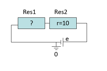
Here we are trying to model an electrical circuit in which two resistors, one known, the other unknown, are connected in series to a voltage generator with an imposed current.
To do this, we need two different resistor models:
A model for which it will be possible to give the ohmic value of the resistor as an argument: this is the Resistor model previously created.
A model for which the ohmic value of the resistor is an unknown.
Modeling the resistor component
The following model, derived from the Dipole model, has an unknown R variable and is subject to ohm’s law.
Model Resistor() extends Dipole[DipoleIndex]
Constants

Variables
R : Resistor;

Elements

Properties
Pin.V-Pout.V = R*I;

End
Modeling the problem
Then we can model the TwoSerialResitor Model by defining two Resistors in the Element part of the Problem: One (Res1) is unkwon, one is known (Res2). We have to post several properties to build the serial connection between the resistors:
The same potential for the input port of Res1 and the output port of Res2.
The algebraic sum of the Current of the input port of Res1 and the output port of Res2 are equal to zero.
And some other properties to connect the generator to the serial circuit:
Set the potential of the ouput port of Res1 to zero.
Set the potential of the input port of Res2 to e.
And finally, we have to impose a condition to the current inside the circuit to be equal to 0.1 A.
Problem TwoSerialResistors
Constants
e : Voltage = 10;

Variables

Elements
Res1 : Resistor(1) ;
Res2 : Resistor(2,10) ;

Properties
Res1.Pin.V = Res2.Pout.V ;
Res1.Pin.I + Res2.Pout.I = 0 ;

Res1.Pout.V = 0 ;
Res2.Pin.V = e ;

Res1.I = 0.1;

End
A zipfile containing the whole DEPS project TwoSerialresistors.proj described in this section can be downloaded here .
Improving the problem representation by modeling a binary node
One of the limitations of the previous model is that the connection between the two resistors is spelled out in the properties to be satisfied in the problem model. It would be interesting to encapsulate these properties within a Node model, which would represent the setting up of a binary connection between two ports. This model have two argments that are the two ports we want to connect. And the kirshoff’s laws are embedded in the Properties part of the Node model (i.e. iso potential of the node and algebraic sum of currents equal to zero).
Note
In DEPS, when we would like to declare an Element as an argument of a model, we name the argument in the list of model arguments and then declare its signature in the Elements part of the model.
Model Node (P1,P2)
Constants

Variables

Elements
P1 : Port[] ;
P2 : Port[];

Properties
P1.V = P2.V ;
P1.I+P2.I = 0 ;

End
In this way, we can rewrite our model of the problem more simply. An instance of Node called Connection is created in the Element part of the problem between the input port of Res1 and the output port of Res2.
Problem  TwoSerialAndNode
Constants
e : Voltage = 10;

Variables

Elements
Res1 : Resistor(1) ;
Res2 : Resistor(2, 10) ;
Connection : Node(Res1.Pin, Res2.Pout) ;

Properties
Res1.Pout.V = 0 ;
Res2.Pin.V = e ;

Res1.I = 0.1;

End
Compiling and solving the problem
A zipfile containing the whole DEPS project TwoSerialResistorsAndNode.proj described in this section can be downloaded via this link .
From an operational point of view, the DEPS project is organised into two packages:
The
Component.depspackage containing the additional quantities useful to the project (Resistance, DipoleIndex), the Port Model and the Resistor Model.
Package Component ;

Uses Universal;

QuantityKind Resistance
Type : real ;
Min  : 0 ;
Max  : +maxreal ;
Dim  : ML2Tminus3Iminus2 ; (* M.L^2.T^-3.I^-2 *)
End

Quantity Resistance
Kind : Resistance ;
Min  : 0 ;
Max  : +maxreal ;
Unit : ohm ;
End

Quantity DipoleIndex
Kind : Integer ;
Min  : 1 ;
Max : 10 ;
Unit : u ;
End


Model Port ()
Constants

Variables
V: Voltage;
expr I: Current;

Elements

Properties

End

Model Dipole (index)
Constants
index: DipoleIndex;

Variables
I: Current;

Elements
Pin: Port();
Pout: Port();

Properties
Pin.I :=  I;
Pout.I := -I;

End

Model Resistor(R) extends Dipole[DipoleIndex]
Constants
R: Resistance;

Variables

Elements

Properties
Pin.V - Pout.V = R*I;

End

Model Resistor() extends Dipole[DipoleIndex]
Constants

Variables
R: Resistance;

Elements

Properties
Pin.V - Pout.V = R*I;

End


Model Node (P1, P2)
Constants

Variables

Elements
P1: Port[];
P2: Port[];

Properties
P1.V = P2.V;
P1.I+P2.I = 0.0;
End
The
TwoSerialResistorsAndNode.depspackage contains the description of the problem.
Package TwoSerialResistorsAndNode ;

Uses Universal, Component  ;

Problem SerialResistors
Constants
e: Voltage = 10.0;

Variables

Elements
Res1:Resistor(1);
Res2: Resistor(2, 10);
Connection: Node(Res1.Pin, Res2.Pout);

Properties
Res1.Pout.V = 0.0;
Res2.Pin.V = e;

Res1.I = 0.1;

End
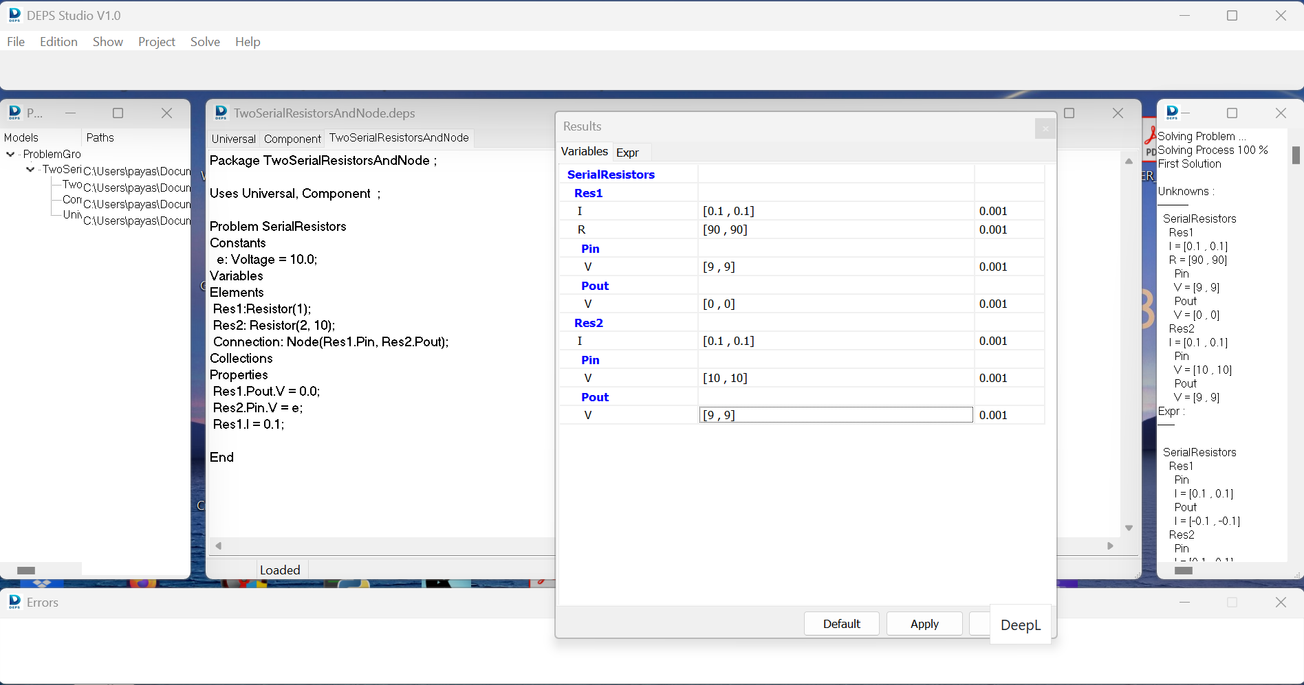
After opening the TwoSerialResistorsAndNode.proj project file in DEPS Studio, we can compile the project (project > build the problem).
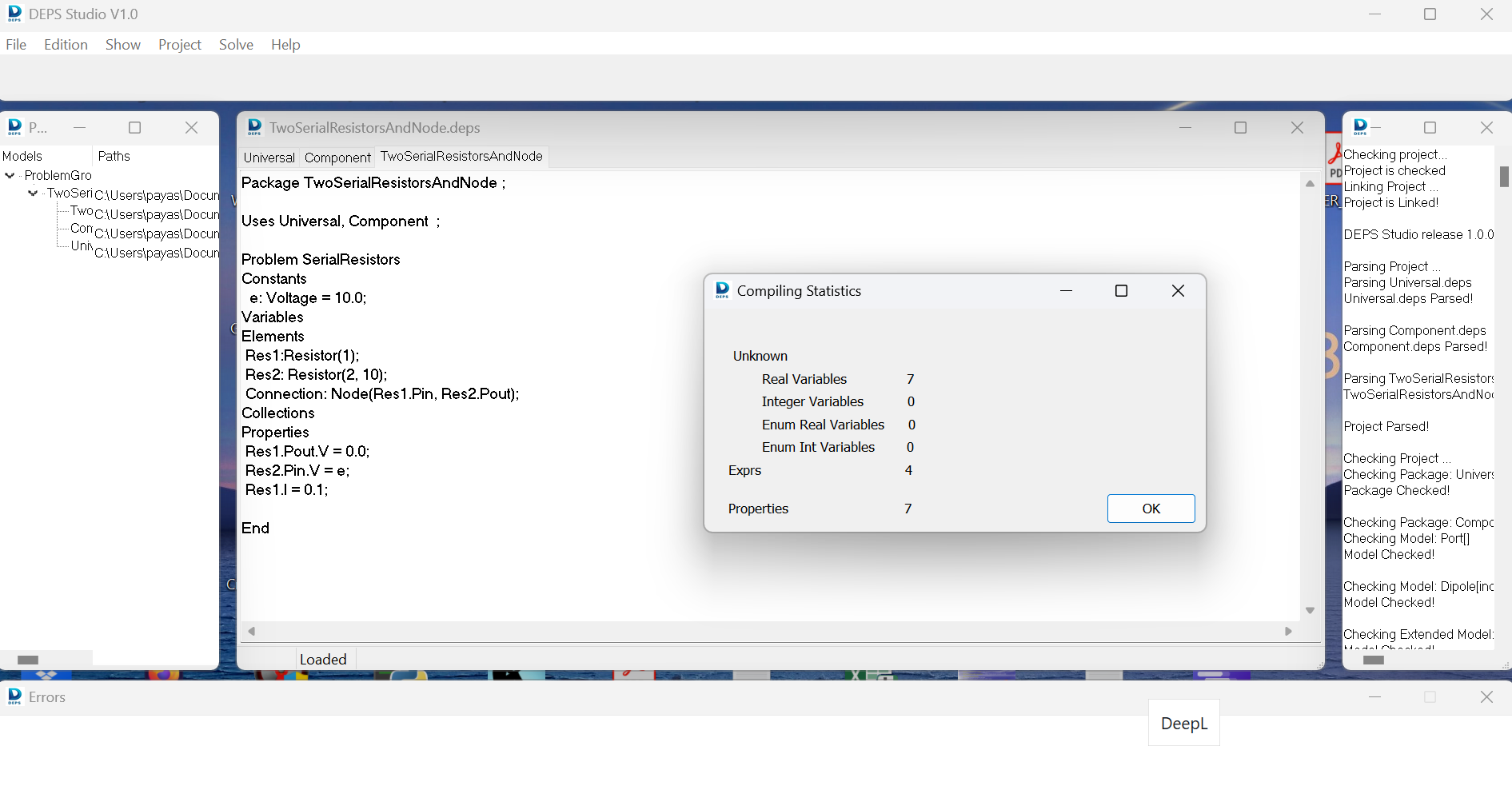
Then the problem can be solved (Solve > Firts Solution).